1Learning Outcomes
Implement a datapath that supports conditional branches (B-Type).
Explain how the input/output signals of the branch comparator help determine (for all B-Type instructions) if a branch is “taken.”
Explain how the PCSel control signal determines the instruction to execute in the next clock cycle.
🎥 Lecture Video
To support branch instructions like beq we must consider state element updates, arithmetic operations, and data selectors.
State element updates:
RegFile: We read two registers
rs1andrs2and compare the valuesR[rs1]andR[rs2]. We do not write to any registers.PC: We read from and write to PC. The value to write now conditionally depends on the result of the two-register comparison, which determines whether a branch is taken:
taken:
pc + 4not taken:
pc + imm
DMEM: No reading nor writing.
Like before, we reuse what already exists in our R-, I-, and S-Type datapath. Even with this, we will need to add three new blocks and some additional control logic.
1.1Branch Comparator
There are three arithmetic operations that branch instructions must (proactively) perform.
pc + 4. This hardware is already in our datapath.pc + imm.Compare
R[rs1]andR[rs2].
We only have one general-purpose ALU available during the EX phase of our single-cycle datapath. We use this ALU to compute pc + imm. We discuss details below
Since this ALU is now busy, we must introduce additional combinational logic to compute a comparison of R[rs1] and R[rs2] within the same clock cycle. We call this new combinational logic block the branch comparator.
We discuss the details of the branch comparator at the end of this section.
1.2MUX for PC input
To conditionally update the input to the PC element, we introduce a new mux that selects between pc + imm and pc + 4 to feed into the PC element. We also therefore introduce a new control signal PCSel to feed into this mux.
These two new blocks are shown in Figure 1. The branch comparator performs a logical operation to compare R[rs1] and R[rs2] and feeds two 1-bit-wide signals, BrEq and BrLT, into control logic. The new mux uses PCSel to update PC based on the branch result.
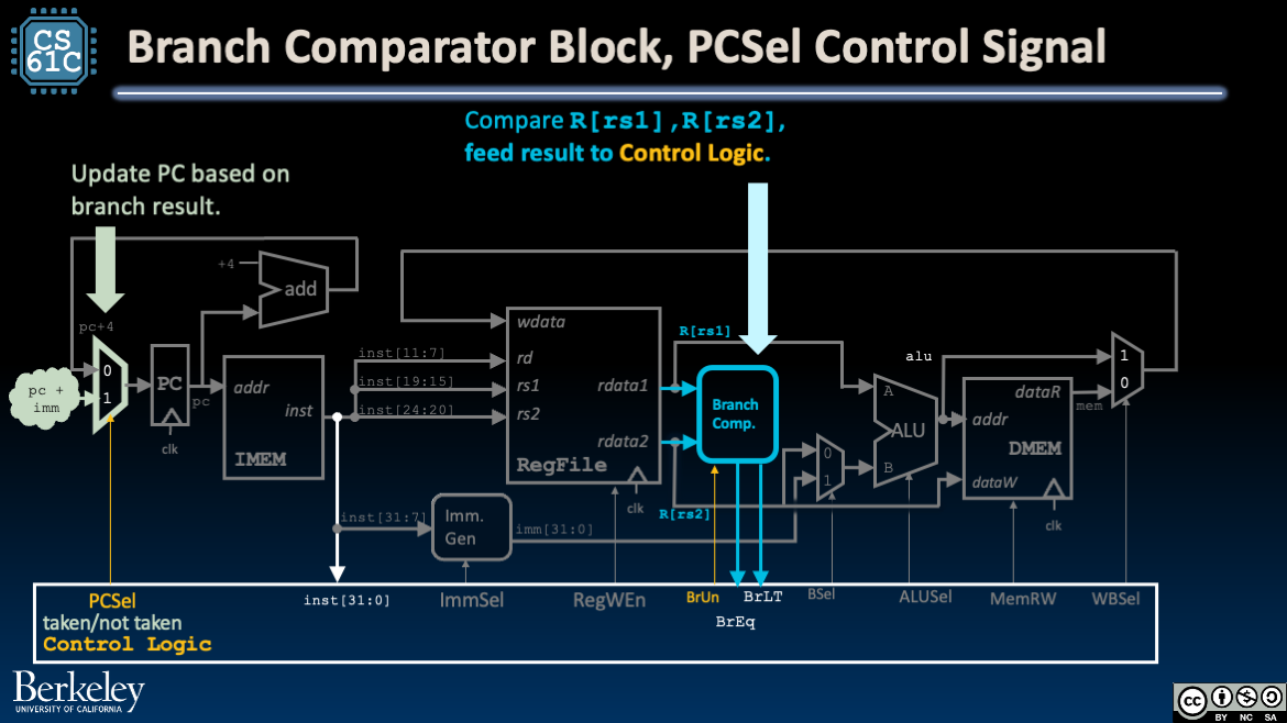
Figure 1:The branch comparator block and the PCSel mux, with PCSel control signal.
1.3MUX for ALU input
We need one more mux in our datapath to compute PC + imm with our existing ALU. The new mux in Figure 2 selects the ALU input A based on a new control signal, ASel.
Set
ASelto1to pass in the program counter valuepc.Set
ASelto0to pass in the register valueR[rs1].
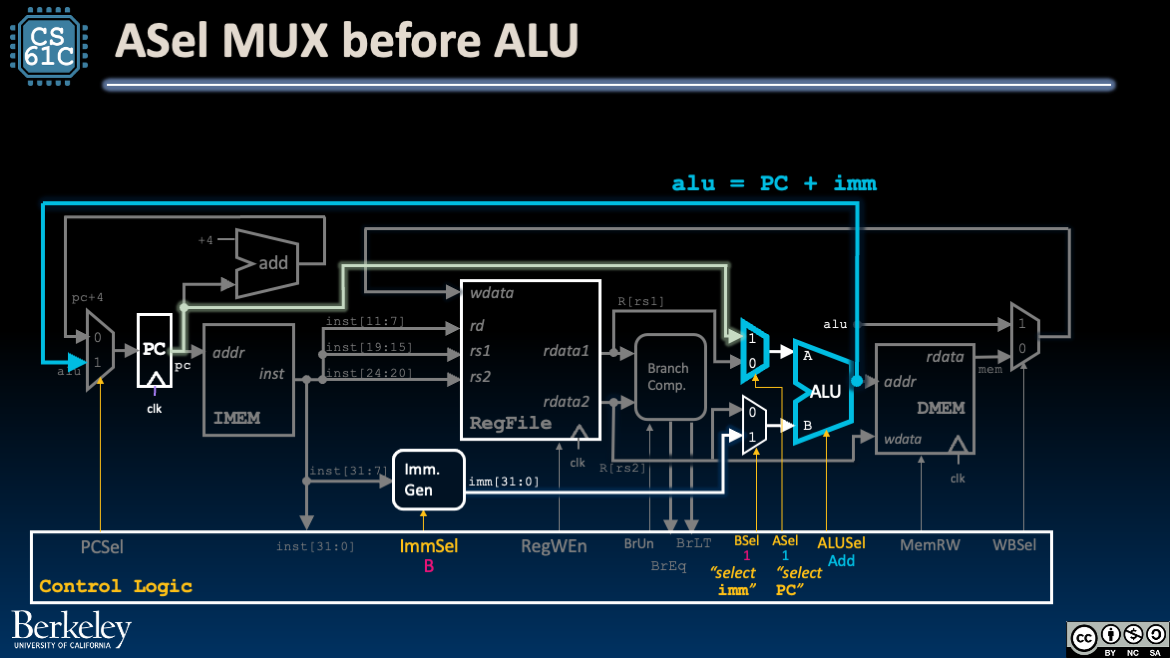
Figure 2:Branches require two muxes with two control signals: PCSel and ASel. The latter determines one of the inputs to our ALU.
1.4Immediate Generator Block
We must also update the Immediate Generator block, ImmGen. Immediates in B-Type are different from I-Type and S-Type and have an implicit trailing zero. Read more in the Immediate Generator section.
2Tracing the Branch Datapath
Let’s walk through the updated datapath for branch instructions (B-Type):
Instruction Fetch: At the beginning of the clock cycle, read PC and fetch the current instruction from IMEM.
Before the next rising clock edge, set up
PCSel, and ensure that the input to PC is stable. IfPCSel=taken, update PC to the output of the ALU. Else, update to next instructionpc + 4.Instruction Decode: Fetch
R[rs1]andR[rs2]from RegFile, build the immediateimmfor B-Type instructions. Also configure control logic (see below).Execute: Compute
pc + immusing the ALU. Because control signals areASel=1andBSel=1, the two muxes before the ALU will selectpcandimm, respectively. BecauseALUSel=Add, the ALU will add these two values together.The branch comparator compares
R[rs1]andR[rs2](doing an unsigned comparison ifBrUn=1) and outputs two signals,BrEqandBrLT, to the control logic.After some delay, the output of the ALU is stable at the mux controlled by
PCSel. Additionally, the control signalPCSelis stable after the control logic uses theBrEqandBrLTsignals to determine whether to take the branch (see details below).Memory: (We don’t access DMEM, so skip this.)
Write Back: (We don’t write to RegFile, so skip this.)
3Branch Comparator Block
The Branch Comparator Block in Figure 3 takes two data inputs and a control input, then outputs the result of comparing the two inputs.
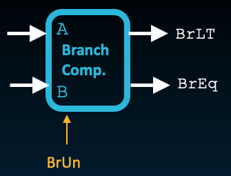
Figure 3:Branch Comparator Block
Table 1:Signals for Branch Comparator. Course project signal names, if different, are in parentheses.
| Name | Direction | Bit Width | Description |
|---|---|---|---|
A (BrData1) | Input | 32 | First value to compare |
B (BrData2) | Input | 32 | Second value to compare |
BrUn | Input | 1 | 1 when an unsigned comparison is wanted, and 0 when a signed comparison is wanted. Control signal. |
BrEq | Output | 1 | Set to 1 if A == B, i.e., the two values are equal. |
BrLT (BrLt) | Output | 1 | Set to 1 if A < B. Perform an unsigned comparison if BrUn=1, and signed otherwise. |
This branch block is used to implement branches on the datapath with logic shown in Figure 4:
!["Datapath diagram with a branch comparator taking values from two registers, using the BrUn flag as a select input, and outputting BrEq and BrLT signals to the control-logic block. The control-logic block also determines PCSel for whether the branch is taken, and receives inst[31:0]."](/build/branch-branch-compar-e2aed60f572ee1c1af5339b9dc20f65d.png)
The control logic sets two control signals:
Sets
BrUnbased on the current instruction, i.e., setsBrUn=1if the instruction isbltuorbgeu.Sets
PCSelbased on branch flagsBrLTandBrEq.
In other words, the control logic subcircuit feeds input into the branch comparator and uses output of the branch comparator to compute additional control signals.[2].
3.1Set PCSel
Note that the two output signals BrLT and BrEq are sufficient for determining the results of all branch comparisons:
beq,bne: CheckBrEqand setPCSelaccordingly.blt(andbltu): IfBrLT=1, thenPCSel=taken.bge(andbgeu): IfBrLT=0, thenPCSel=taken. For integers and , checking is equivalent to checking .
Review Control Signals for Stores for an explanation of “don’t care.”
See a later section for more details.