1Learning Outcomes
Implement a datapath that supports R-Type and I-Type arithmetic/logical instructions by reusing the ALU and adding an immediate generator block.
Explain why a MUX is needed at the
Binput of the ALU.Design an immediate generator block that outputs a 32-bit immediate value from a 32-bit instruction.
Extend the immediate generator block to support multiple immediate formats based on instruction format: I-, S-, B-, J-, and U-Type.
🎥 Lecture Video
2Building a R-Type + addi processor
Let’s extend our R-Type datapath to support I-Type arithmetic and logical instructions, starting with addi. To support addi:
RegFile: We read one register
rs1and write one registerrd. The value to write isR[rs1] + imm, the sum of the read register value and an immediate.PC: We read from and write to PC. The value to write is
pc + 4.
The addi instruction updates the same two states as R-Type instructions. But we now need to build an immediate imm!
To do so, we reuse what already exists in our R-Type datapath, then consider what additional blocks we need to add. In Figure 1, we notice:
We can leave the
PC = PC + 4portion of the datapath unchanged.We can reuse much of the read/writing of the RegFile portion of the datapath. We still want to read
R[rs1]and writeR[rd].We want add two 32-bit values, so we should probably reuse the
ALUto “add.”We can keep the wire to ALU’s input signal
Aunchanged.We want to change the input signal
Bto be set to an immediateimmso that the ALU computesalu = R[rs1] + imm.
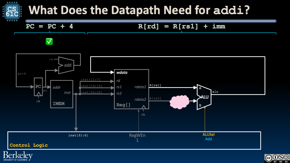
Figure 1:addi: Reuse PC = PC + 4 loop and ideally the “add” operation in the ALU.
We therefore need additional logic that, for I-Type instructions, feeds in an immediate imm to ALU input B (instead of R[rs2], used for R-Type). Figure 2 introduces the two new blocks and wires them to our existing datapath:
A new mux selects the ALU input
Bbased on a new control signalBSel. Read about muxes/multiplexors in a previous section.Set
BSelto1to pass in the immediateimm.Set
Bselto0to pass in the register valueR[rs2].
A new block, the immediate generator, generates a 32-bit value
immfrom the instruction bitsinst.
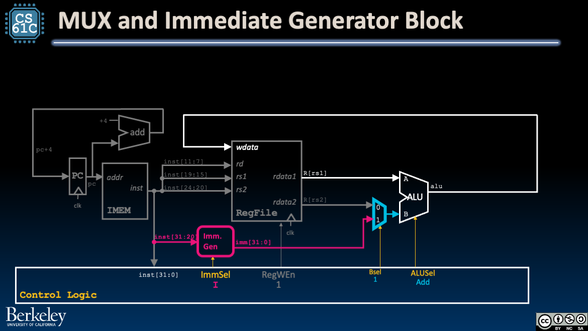
Figure 2:addi: Add the BSel mux and the ImmGen block.
3Tracing the addi Datapath
Let’s walk through the addi datapath with this new knowledge.
Figure 3:The addi datapath. Use the menu bar to trace through the animation or access the original Google slides.
Instruction Fetch: Increment PC to next instruction (see R-Type datapath). Read the instruction
instfrom IMEM.Instruction Decode:
Read
R[rs1]from RegFile (see R-Type).Set up the destination register
rdfor writing.Build the immediate
imm. For I-Type instructions, wire the upper 12 bits of the instructioninst[31:20]to the input to the Immediate Generator block.Configure control logic.
Configure
ImmSeltoI-type immediates (for now, we only have one type of immediate).Set
RegWEnto1.Set
BSelto1.Set
ALUSeltoAdd.
After some delay, the immediate generator block updates its output signal
immto the appropriate sign-extended 32-bit immediate value, register valueR[rs1]is read, and control signals are set.Execute: Because the control line
BSel=1selects the generated immediateimmfor ALU inputB, our ALU computesR[rs1] + imm.Memory: (We don’t access DMEM, so skip this.)
Write Back: Write ALU output to the destination register by connecting
aluto RegFile’swdatainput (see R-Type).Around the next rising clock edge,
wdata,RegWEn, andrdshould be held stable through setup and hold time of RegFile.
4Immediate Generator Block
We encourage revisiting this section after reading a few more example datapath traces.
!["ImmGen block for I-type immediates: input is inst[31:20] and output is imm[31:0] using sign extension. Block is controlled by ImmSel control signal."](/build/element-immgen-ab13f029a405fb1772ba0f2a24665521.png)
Figure 4:Immediate Generator Block
Table 1:Signals for Immediate Generator. Course project signal names, if different, are in parentheses.
| Name | Direction | Bit Width | Description |
|---|---|---|---|
| Input | inst (Instruction) | 32 | The instruction being executed |
| Input | ImmSel | 3 | Value determining how to reconstruct the immediate |
| Output | imm (Immediate) | 32 | Value of the immediate in the instruction |
Recall that the bits of the immediate are stored in different bits of the instruction, depending on the type of the instruction. The ImmSel signal, which is implemented in the control logic, will determine which type of immediate this subcircuit should generate.
The immediate storage formats are listed below in Table 2.
Table 2:Immediate Storage Formats from the RISC-V Green Card.
| Type | ImmSel (default) | Bits 31-20 | Bits 19-12 | Bit 11 | Bits 10-5 | Bits 4-1 | Bit 0 |
|---|---|---|---|---|---|---|---|
| I | 0b000 | inst[31] | inst[30:20] | ||||
| S | 0b001 | inst[31] | inst[30:25] | inst[11:7] | |||
| B | 0b010 | inst[31] | inst[7] | inst[30:25] | inst[11:8] | 0 | |
| U | 0b011 | inst[31:12] | 0 | ||||
| J | 0b100 | inst[31] | inst[19:12] | inst[20] | inst[30:21] | 0 | |
Observations/reminders:
You should treat I*-type immediates as I-type immediates, since the ALU should only use the lowest 5 bits of the B input when computing shifts.
Recall that all immediates are 32 bits and sign-extended. Sign extension is shown in Table 2 as
inst[31]repeated in the upper bits.U-type instructions require left-shifting the immediate by 12 bits (e.g.
luiis written asrd = imm << 12on the reference card). This should be done in the immediate generator so that the datapath doesn’t need to perform any extra shifting.
In the following subsections, we “iteratively” build the immediate generator to support I-Type, then S-Type, then B-Type. We leave the implementation of J-Type and U-Type immediates to you and the course project.
4.1I-Type
First, suppose our datapath only supported immediates from I-Type instructions. In this case, the immediate generator would perform two operations as shown in Figure 5.
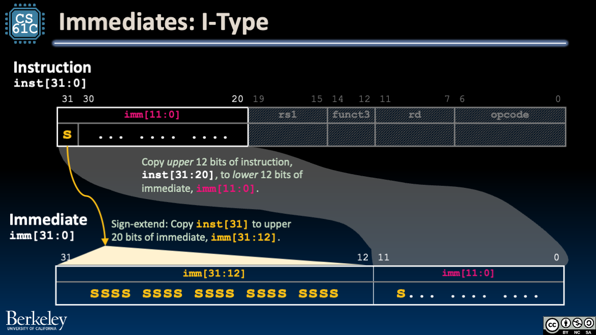
Figure 5:Immediate Generator Block: I-Type
Show Explanation
imm[31:12]: Sign-extend. Copy the sign bitinst[31]to the upper 20 bits of the immediate,imm[31:12].imm[11:0]: Wire. Directly connect the two upper 12 bits of the instructioninst[31:20]to the lower 12 bits of the outputimm[11:0].
4.2I-Type, S-Type
Next, suppose our datapath supported immediates from both I-Type and S-Type instructions. The immediate generator must set the lower bits imm[4:0] based on the immediate type. In Figure 6, we implement this selection with a MUX.
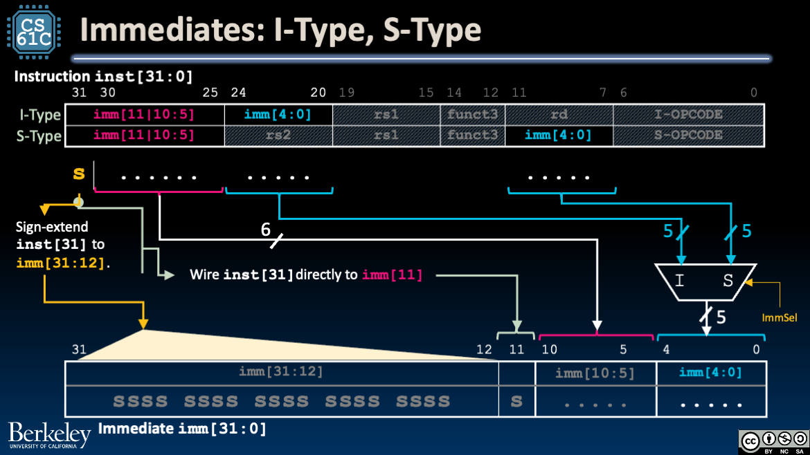
Figure 6:Immediate Generator Block: I-Type, S-Type
Show Explanation
imm[31:12]: Sign-extend. In both instruction formats,inst[31]is the sign bit of the immediate. Copy the sign bitinst[31]to the upper 20 bits of the immediate,imm[31:12].imm[11:5]: Wire. Directly connect the instruction bitsimm[31:25]to the outputimm[11:5].imm[4:0]: Select. Select the five bits to fillimm[4:0]:inst[24:20]if I-Type, andinst[11:7]if S-Type.
4.3I-Type, S-Type, B-Type
Finally, suppose our datapath supports I-Type, S-Type, and B-Type instructions. The immediate generator design is shown in Figure 7, now with even more MUXes.
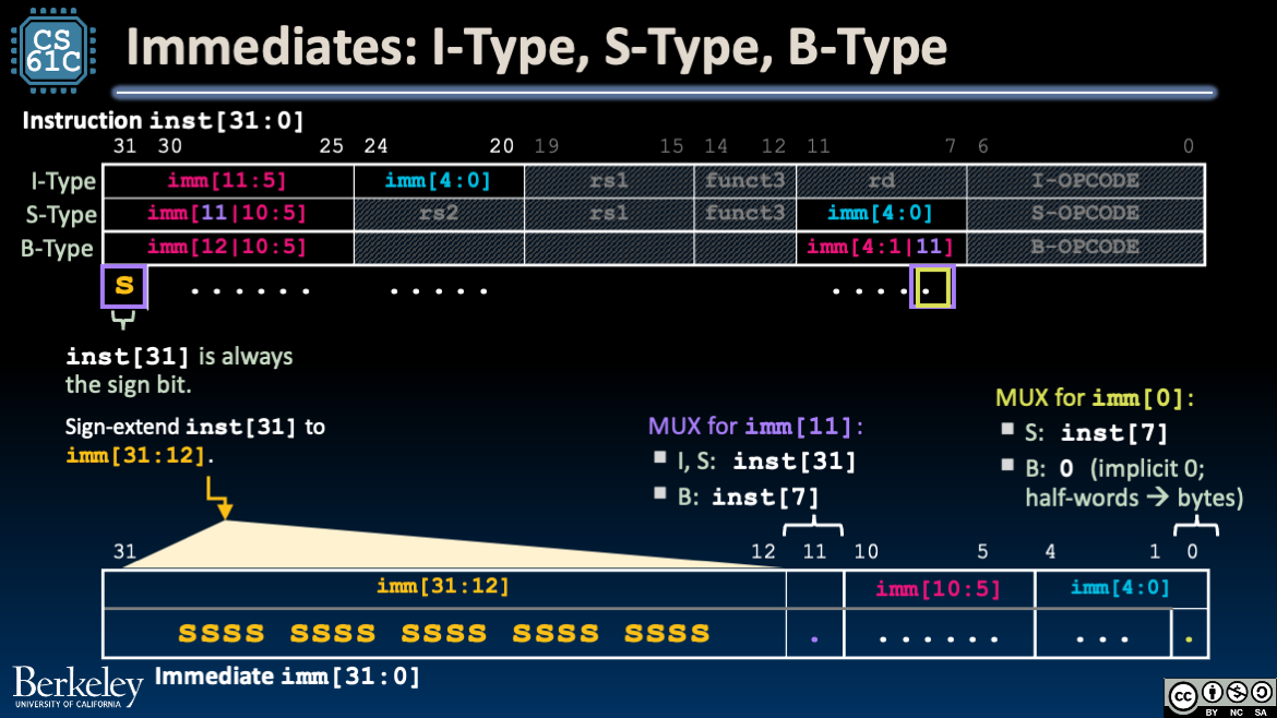
Figure 7:Immediate Generator Block: I-Type, S-Type
Show Explanation
imm[31:12]: Sign-extend. In all three instruction formats,inst[31]is the sign bit of the immediate. Copy the sign bitinst[31]to the upper 20 bits of the immediate,imm[31:12].imm[11]: Selectinst[31]if I-Type or S-Type, andinst[7]if B-Type.imm[10:5]: Wire. Directly connect the instruction bitsimm[30:25]to the outputimm[10:5].imm[4:1]: Select.inst[24:20]if I-Type, andinst[11:8]if S- or B-Type.imm[0]: Select.inst[20]if I-Type,inst[7]if S-Type, and0(implicit) if B-Type.
4.4Course Project Details
Table 3:Default ImmSel encodings for the course project. You are welcome to pick your own.
ImmGen Value (for Project) | Immediate Type |
|---|---|
0b000 | I |
0b001 | S |
0b010 | B |
0b011 | U |
0b100 | J |